To connect your Zumo or any other electrical device requiring a switched power supply, you can tap into the CAN-Bus connector on the 'tank'.
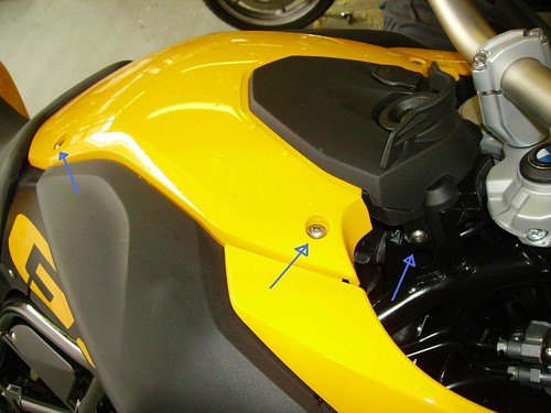
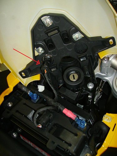
To get under the fake tank, you need to remove the seat and six torx bolts. Four on the top tank panel, and two either side of the headstock, mounted in the black plastic that forms part of the ignition/socket assembly:
![Image]()
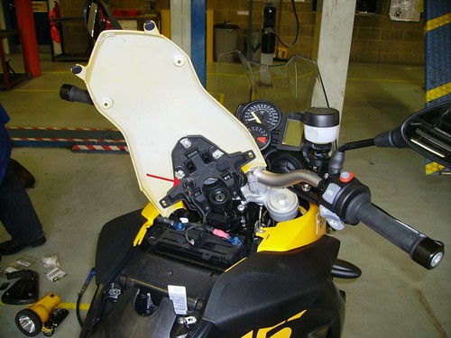
The tank panel now lifts straight off but be careful of the power socket wiring underneath:
![Image]()
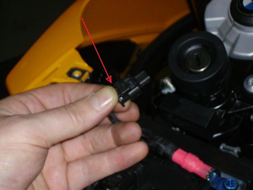
A closer look at the power socket wiring connector:
![Image]()
The wires are attacked with a spring clip. You have to press down with your thumb to release it, then pull straight off the socket:
![Image]()
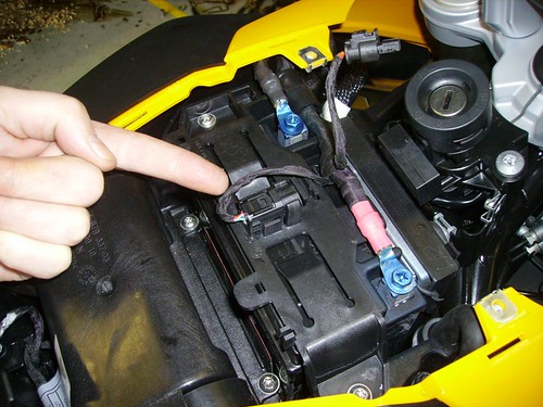
Ooh look, what is this mysterious black box thing attached directly on top of the battery? Notice as well the space between the battery and the airbox. This vertical gap will accomodate the newer Autocom units. Or a secret supply of currency.
![Image]()
Pull it out of the mounting clips, and remove the black cap. There is another spring clip holding the black cap on. And inside? This:
![Image]()
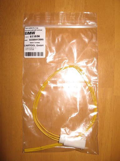
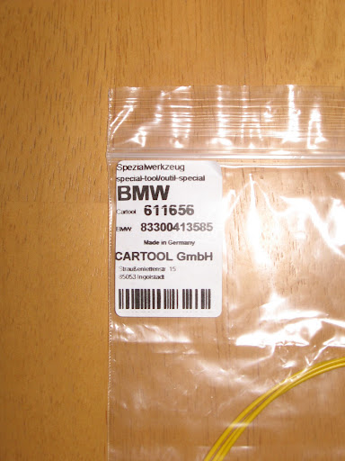
Which is our very obviously placed GPS connector. To connect your GPS unit to this can-bus controlled switched supply that stays on for a few minutes when you turn the engine off, you will need part number 80 00 0 611 656 (UK) or 83 30 0 413 585 (US - can someone verify please?) from your friendly local BMW Dealer:
![Image]()
To make the cable,
See better instructions halfway down this page, but in brief:
You could buy the cable ready-made from Touratech if you don't want to butcher your original cable.
CAN-Bus Ready Made Cable from Touratech
![Image]()
Alternative Options:
You could wire your Zumo directly back to the battery with an in-line fuse. You can buy the ready made cable from touratech:
![Image]()
Or you could wire your cable to a DIN plug and plug it into the DIN accessory socket next to the ignition. The plug cost around £3, but you can buy a ready-made cable from touratech:
![Image]()
Other Electrical Connections:
NOTE: Powerlet and BMW/DIN sockets are the same size, and the plugs are interchangeable. They are the same thing. Cigar sockets & plugs are bigger, like the one in your car.
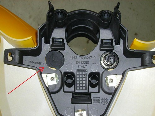
You can add an additional accessory socket to the right of the ignition key and power it from the CAN-Bus connector. There is a cut-out on the underside of the 'tank' panel to show where to place the additional socket You do not need an in-line fuse for CAN-Bus connections.
![Image]()
You can buy a socket kit ready-made to plug into the CAN-Bus from Powerlet:
![Image]()
CAN-Bus can support up to 5amps, so electrical devices with a greater power draw (such as a heated jacket perhaps) will need an accessory socket. You could wire an additional accessory socket (BMW/DIN/Powerlet or cigar lighter size) to the right of the ignigition key (see picture above) and wire it back to the battery directly - this supply would not switch off with the ignition. You will need an in-line fuse between the socket and the battery.
You can buy a socket kit for the fake-tank cut-out, ready-made with inline fuse to wire directly back to the battery from Powerlet:
![Image]()
You can also buy handle-bar mounted sockets to wire back to the battery.
Touratech do a full dashboard for the 800GS/650GS(Twin) that includes an additional accessory socket.
Powerlet do a full range of Powerlet sockets and plugs, as well as Cigar sockets & plugs and SAE 2-pin connectors.
They also do adapters beween the different plug types.
Also a full range of power cables to power your iPod, radar detector, USB, heated clothing etc. from a Powerlet socket.
Finally, if you have several devices to wire back to the battery you might consider a fuse panel, like the one AP-1 Centech Fuse Panel from Nippy Norman in the UK
![Image]()
This little box means only one connector to the battery, then you can quickly add wires to the box and each line is fused, meaning no need for in-line fuse.
Hope this helps someone.
To get under the fake tank, you need to remove the seat and six torx bolts. Four on the top tank panel, and two either side of the headstock, mounted in the black plastic that forms part of the ignition/socket assembly:
The tank panel now lifts straight off but be careful of the power socket wiring underneath:
A closer look at the power socket wiring connector:
The wires are attacked with a spring clip. You have to press down with your thumb to release it, then pull straight off the socket:
Ooh look, what is this mysterious black box thing attached directly on top of the battery? Notice as well the space between the battery and the airbox. This vertical gap will accomodate the newer Autocom units. Or a secret supply of currency.
Pull it out of the mounting clips, and remove the black cap. There is another spring clip holding the black cap on. And inside? This:
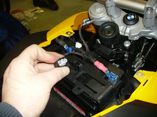
Which is our very obviously placed GPS connector. To connect your GPS unit to this can-bus controlled switched supply that stays on for a few minutes when you turn the engine off, you will need part number 80 00 0 611 656 (UK) or 83 30 0 413 585 (US - can someone verify please?) from your friendly local BMW Dealer:

To make the cable,
See better instructions halfway down this page, but in brief:
- Get your Zumo cable and cut the fuse off (CAN-Bus doesn't need fuses). Leave as much cable length as you think you'll need. Strip back and tin the red and black cables and slide heat-shrink on.
- On the CAN-Bus connector, you can trim Wire 2 right back, its not needed. (or leave it longer and heat-shrink it into place with the other cables.
- On the CAN-Bus connector, strip back wires 1 & 2 and tin them.
- Solder the black Zumo cable negative/earth to wire 1 on the connector
- Solder the red Zumo cable (positive/live) to wire 3 on the connector
- Heat shrink/PVC tape around the joints.
- Job Done.
You could buy the cable ready-made from Touratech if you don't want to butcher your original cable.
CAN-Bus Ready Made Cable from Touratech

Alternative Options:
You could wire your Zumo directly back to the battery with an in-line fuse. You can buy the ready made cable from touratech:

Or you could wire your cable to a DIN plug and plug it into the DIN accessory socket next to the ignition. The plug cost around £3, but you can buy a ready-made cable from touratech:

Other Electrical Connections:
NOTE: Powerlet and BMW/DIN sockets are the same size, and the plugs are interchangeable. They are the same thing. Cigar sockets & plugs are bigger, like the one in your car.
You can add an additional accessory socket to the right of the ignition key and power it from the CAN-Bus connector. There is a cut-out on the underside of the 'tank' panel to show where to place the additional socket You do not need an in-line fuse for CAN-Bus connections.
You can buy a socket kit ready-made to plug into the CAN-Bus from Powerlet:

CAN-Bus can support up to 5amps, so electrical devices with a greater power draw (such as a heated jacket perhaps) will need an accessory socket. You could wire an additional accessory socket (BMW/DIN/Powerlet or cigar lighter size) to the right of the ignigition key (see picture above) and wire it back to the battery directly - this supply would not switch off with the ignition. You will need an in-line fuse between the socket and the battery.
You can buy a socket kit for the fake-tank cut-out, ready-made with inline fuse to wire directly back to the battery from Powerlet:

You can also buy handle-bar mounted sockets to wire back to the battery.
Touratech do a full dashboard for the 800GS/650GS(Twin) that includes an additional accessory socket.
Powerlet do a full range of Powerlet sockets and plugs, as well as Cigar sockets & plugs and SAE 2-pin connectors.
They also do adapters beween the different plug types.
Also a full range of power cables to power your iPod, radar detector, USB, heated clothing etc. from a Powerlet socket.
Finally, if you have several devices to wire back to the battery you might consider a fuse panel, like the one AP-1 Centech Fuse Panel from Nippy Norman in the UK

This little box means only one connector to the battery, then you can quickly add wires to the box and each line is fused, meaning no need for in-line fuse.
Hope this helps someone.
")